Materials
Prepare the Mesh
This tutorial will cover the procedure for integrating a new weapon into Enfusion Workbench. While it may focus more on Blender users, other software users shouldn’t worry, as most of the processes shown here can be similarly performed in other software.
Object Orientation
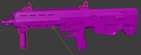
One of the most important thing to begin with is making sure that your model is properly orientated. As per Arma Reforger:FBX Import page:
Info
Everything must be oriented as pointing along/towards the Y+ axis in Blender and 3dsMax and along the Z+ axis in Maya.
That means, when you are importing an A3/external weapon you need to rotate it by 90 degrees to the left.
Object Cutting
You may already have some bits present in the mesh. Since Enfusion allows you to assemble a weapon from multiple parts, we will split our mesh into several separate objects to achieve much higher customization of the weapon.
In this case, the sample contains two parts that could potentially be moved to separate files, allowing you to have three variants in total quite easily. As shown in the video above, the grip and iron sights were moved to separate FBX files. The magazine was already separated for that particular mesh, so the only remaining task is to add slot points for those accessories.
Object Naming
When it comes to naming, there are a few important rules to keep in mind:
- _LODx suffix is used to indicate Level of Details.
- UBX_, UCX_, USP_, UCS_, UCL_, UTM_ prefixes are used to mark Colliders.
- OCC_ prefix is used for Geometry Occluders.
Besides that, there are also additional guidelines regarding the naming of objects—slot/snap points naming convention—which do not affect how the mesh is processed by the engine (like those mentioned above) but are there to ensure consistency. It’s also worth noting that some base weapon prefabs use some of these names by default. They can be changed, but it’s strongly advised to follow these rules nevertheless.
Add Slots/Snap Points
If you have experience with Arma 3 modding, the concept of having slots and snap points should be fairly familiar to you. These dummy objects serve as memory points. However, there is one major difference: you no longer need to place two points to create an axis. Instead, the rotation of the dummy object is used.
In Blender, you can use one of the empty objects, such as Plain Axis, to create these helper points.
![]()
Please notice the Plain Axis gizmo - this is the orientation of the model.
Make sure that your empty object is properly aligned.
![]()
Info
One easy method to ensure slot and snap points are correctly aligned is to create the slot points while the mesh is still in one piece. Then, copy and paste the mesh and empty socket to a new empty scene. After that, the only thing left to do is rename slot_XX to snap_XX.
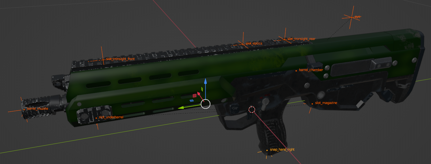
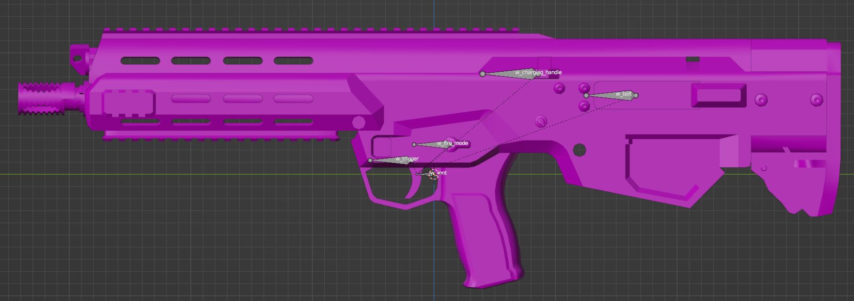
On Sample Weapon, the following slots were created:
- slot_ironsight_front & slot_ironsight_rear - slots for picatinny mounted ironsights
- slot_magazine - slot for magazine well
- slot_optics - slot for top-mounted optics
- slot_underbarrel - slot for bottom-mounted accessories like bipods
Additionally, the following empty objects were created for various components:
- snap_hand_right - IK target for the right hand when using the weapon deployment feature
- snap_hand_left - IK target for the left hand when using the weapon deployment feature
- barrel_chamber & barrel_muzzle - these points are used in MuzzleComponent to determine the location and direction where the bullet is spawned
- eye - point for aiming down sight view, used in SightsComponent
Colliders & Material Names
Colliders are a special type of object used to calculate various kinds of collisions, whether it be for physics simulation or tracing bullet penetration. There are a few rules regarding these colliders, most of which are listed on the FBX Import - Colliders usage page.
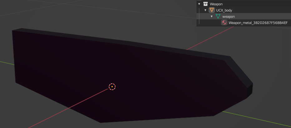
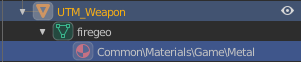
Collider with Weapon Layer Preset:
 Collider with FireGeo Layer Preset:
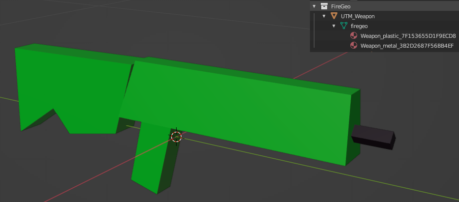
A weapon requires at least one collider with the Weapon layer preset. Without it, weapon actions like equip will be missing. If your geometry is simple enough, you can use one collider for both weapon and fire geometry collisions. Otherwise, you might need two colliders:
- One for Weapon collision - this should be a very simple collider (e.g., convex).
- Another for FireGeo collision - this can be more detailed; a trimesh can be used to provide the best experience.
When importing assets from previous Arma games, you are likely to already have convex components ready from Geometry, Fire Geometry, View Geometry, or Geometry Physx LODs. In this case, the Fire Geometry LOD from Arma 3 was used as FireGeo, and the mesh from Geometry LOD was used for the Weapon layer.
You might ask how to assign Layer Presets. If you are using Blender, there is a handy tool called Objects Tool, which is part of Enfusion Blender Tools, to assist you with assigning the correct game materials and layer presets on colliders. Otherwise, refer to the FBX Import page for instructions on how to set that parameter in 3DS Max or Maya.
Info
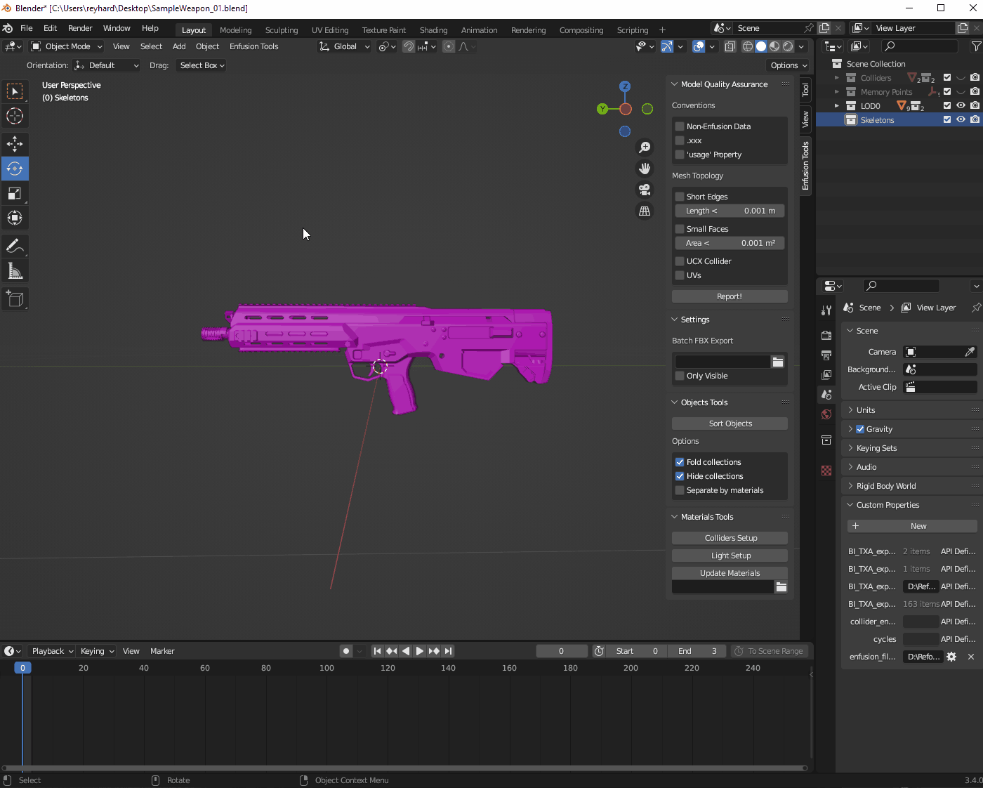
You can use Model Quality Assurance to verify if your colliders are convex by checking UCX Collider option.
Skeleton Setup & Mesh Rigging
Skeleton Creation
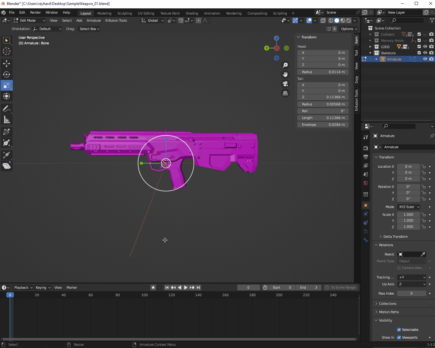
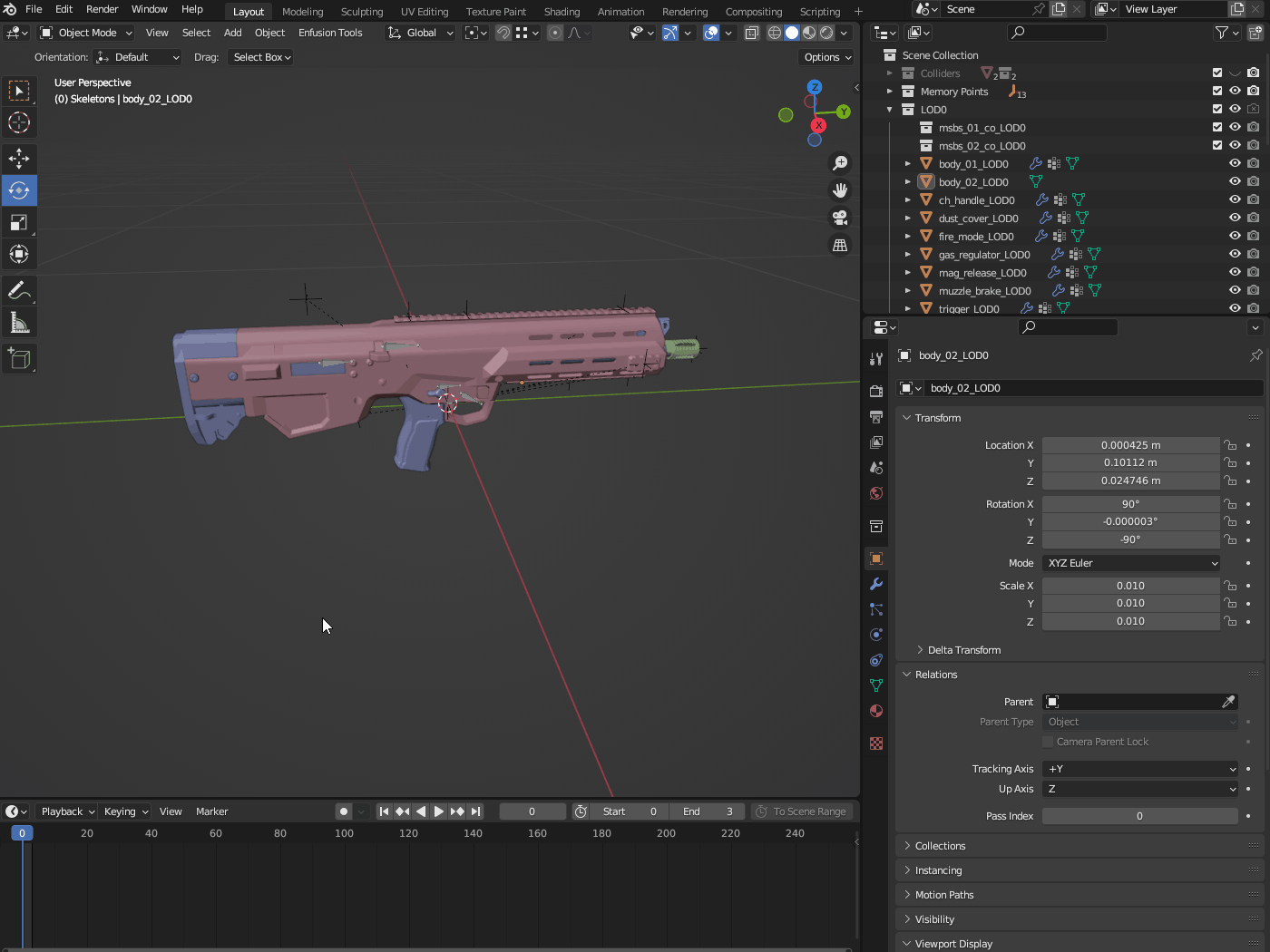
Whether it’s a new model or a mesh imported from P3D, it will most likely be necessary to prepare a skeleton. In Blender, skeletons are called Armatures, and their creation process is quite straightforward. Start with the creation of the Armature itself. This can be done by selecting the Armature option from the Add menu in the top section of the viewport while in Object mode.
Warning
It is recommended to name your armature Armature to avoid an artificial bone in the skeleton hierarchy when the mesh is imported into Workbench. While this might not cause issues with rifles, it is essential when importing character-related gear.
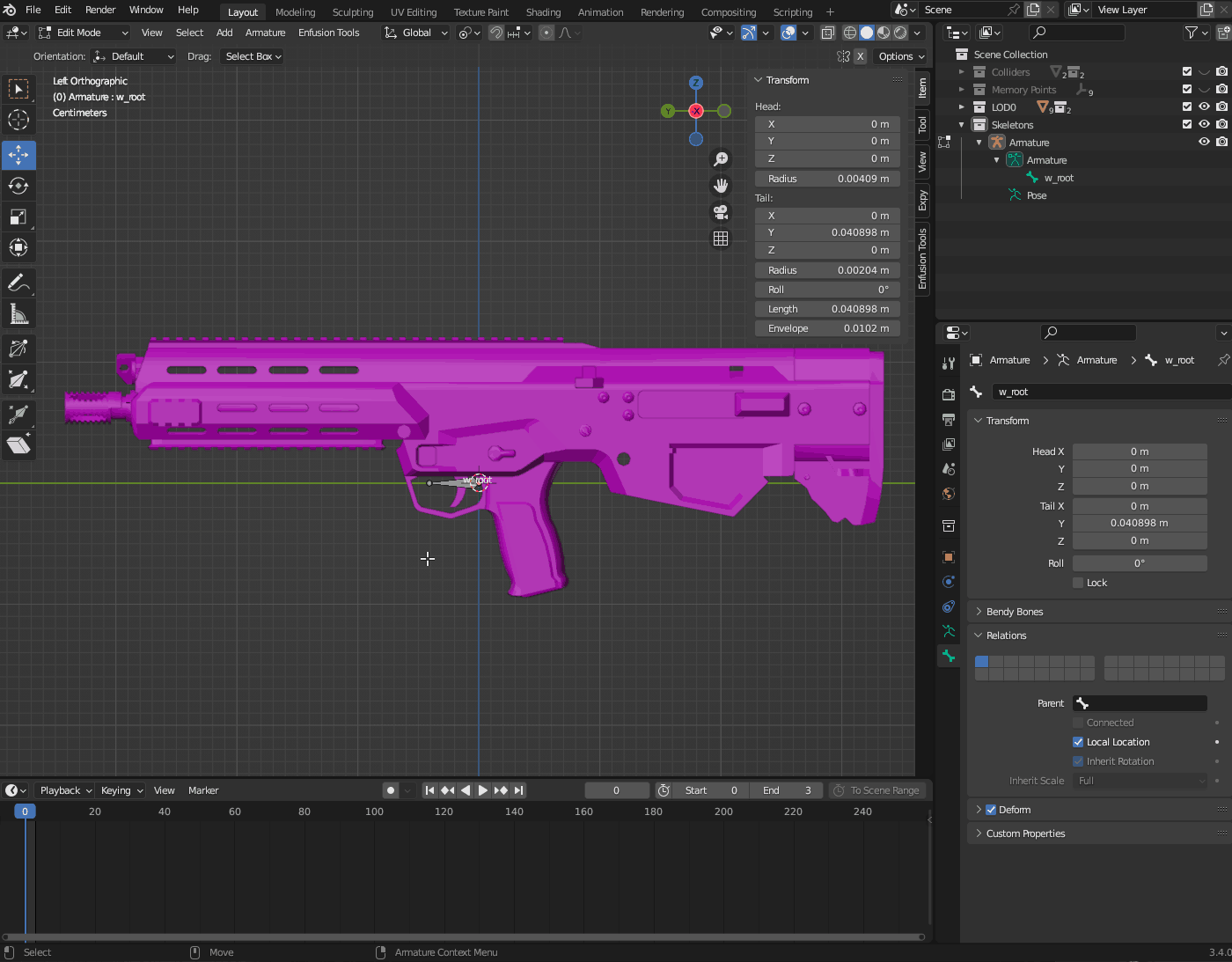
Once it is created, you might notice that the root bone is quite large and may want to resize it. To do this, switch to Edit Mode, select the Bone, and then reduce its size to a reasonable level.
Warning
Armature should be located at 0,0,0 point and be using 1.0 scale. Otherwise you might encounter some problems when trying to animate it in Blender at a later stage.
The next step is to rotate this bone towards the front of the weapon and then rename it to w_root. This bone will serve as the root bone of the mesh.
Bones Creation
After the basics of the armature are done, it is time to add bones for all animated parts of the weapon. While in Edit Mode and with Armature selected, you can add new bones through either of these methods:
- Add → Single Bone option in the top bar of the viewport
- By duplicating a bone already present in the armature, like w_root
If you choose the first option, you will need to resize and rotate the new bone to the desired size. Duplication doesn’t have this issue, so it was chosen to create the fire mode switch bone - w_fire_mode.
It is also important to maintain the hierarchy of bones. In this case, all bones responsible for moving parts of the weapon, like w_fire_mode, should be parented to w_root. This can be done by selecting the bone in Edit Mode and then changing the Parent property in the Relations section of the Bone properties tab.
Info
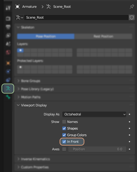
Consider setting the bone visibility to In Front - this will help with placement of the bones.
There are a few things to keep in mind when creating bones. Below is a list of those considerations:
- Bones will serve as axes for any further motion, so try to place them in spots that would result in reasonable motion, like the center of the fire selector pivot point or the center of the bolt.
- Keep Y+ orientation of the bones. This is especially handy if an action uses the center of the bone for operations.
- While it’s not necessary, it is recommended to use the vanilla naming convention for bones. This is particularly useful when dealing with animation export, as vanilla animation export profiles expect such bone names.
- It is still possible to use custom names, but this might require custom export profiles. More about this will be mentioned in the chapter covering weapon animation.
With this knowledge in mind, it should be possible to create the rest of the bones like w_trigger, w_charging_handle, and w_bolt.
Mesh Skinning
Skinning of the mesh depends on the software that you are using and if you don’t know how to do it in software of your choice, it is recommended to search for some tutorials on the web what skinning of bones is.
Info
If you’ve imported your model from P3D via Enfusion Blender Tools then you will have some vertex groups already - in this case you can try to rename those so they match the skeleton bone names.
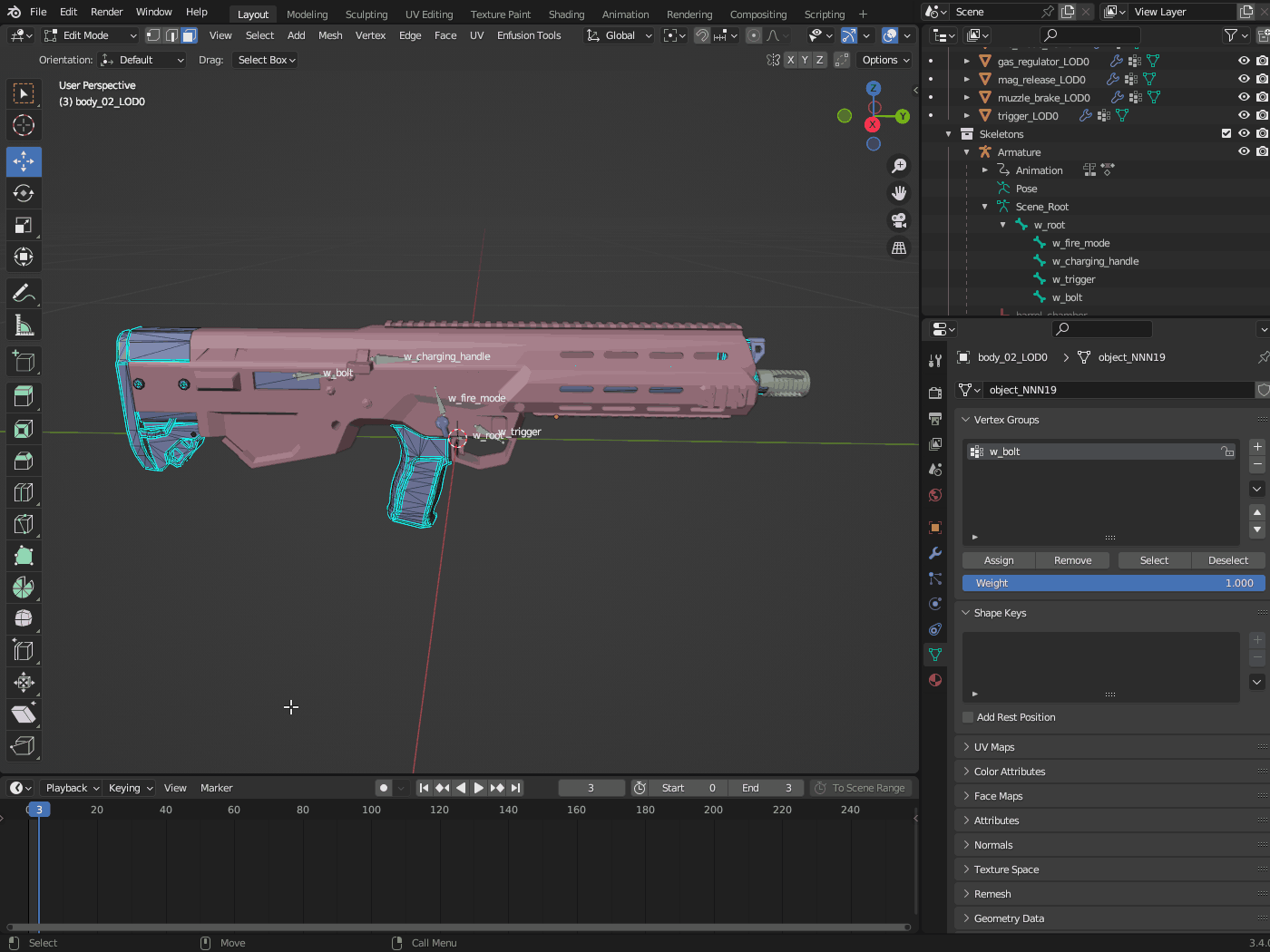
If you are using Blender, here is a short instruction on how to quickly set up skinning on an object. In the example below, the w_bolt bone will be set:
- Switch to Object Mode.
- Select the object you want to skin - in this case, it is body_02_LOD0.
- In the Modifiers Properties tab, add the Armature modifier via the Add Modifier button.
- In the Object property of the Armature modifier, select the Armature (skeleton) that should influence this object - in this case, it is Armature.
- In Object Data Properties, expand the Vertex Group panel.
- Switch to Edit Mode and then activate face selection mode.
- Select the faces that should belong to the bolt.
- In the Vertex Group section, click on the plus button to Add Vertex Group.
- Double-click with the Left Mouse Button on it and change the name of that new vertex group from Group to w_bolt.
- Click on the Assign button in the Vertex Groups section (assuming you still have the bolt faces selected in the viewport) - this will assign your current selection in the viewport to the w_bolt vertex group with full influence (influence is controlled by the Weight property).
 At this stage the w_bolt bone should be successfully rigged but that is not the end of the process!
Warning
Below section applies to any 3D software!
When creating skinned objects, Enfusion Workbench expects that the whole object is skinned to a bone.
Warning
Otherwise, the importer will try to “fix” it by skinning the remaining faces to some root bone, and you will see the following message in the console log:
RESOURCES (W): Missing some mesh skinning weights (Object_LOD0). Weighting them to root
In Blender, this means that any object with an Armature modifier must be fully skinned to some existing bone through vertex groups. In this case, it means that all faces, besides those belonging to the w_bolt vertex group, on the body_02_LOD0 object must be skinned to the w_root bone. This was done by selecting the faces belonging to w_bolt and then inverting the selection using the Ctrl + I shortcut. After that, a new vertex group called w_root was created, and the current selection was assigned to it via the Assign button.
Colliders Rigging
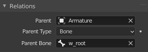
If you have an animated collider, please keep in mind that only trimesh colliders can be skinned. In all other cases, you have to use 100% weight.
In Blender, it gets even more tricky. You need to use Object Relations (in the Object tab) if you want to connect a non-trimesh collider to a skeleton bone.
Info
It is also recommended to parent slots on the weapon to the Armature - it is not necessary to parent it to the w_root bone though. This should make it easier to snap magazine in the reload sequence for instance.
FBX Export Settings
Most of the general rules can be found on the FBX Import page. In principle, when exporting from software like 3DS Max, you need to ensure that you are exporting in binary format in version 2014/2015. Furthermore, Triangulation and Preserve Edge Orientation should be turned off.
For Blender, there are three important things to keep in mind when exporting FBX:
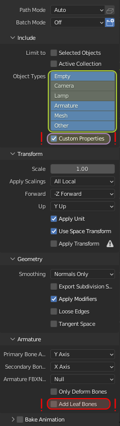
- Object Types:
For an animated object like a weapon you need to have checked at least:
Empty - which handles all the snap points
Armature - exports the skeleton of your weapon
Mesh - self explanatory
- Custom Properties:
Without this option all the custom properties like LayerPresets would be lost!
- Leaf bones:
Leaf bones are completely unnecessary in Enfusion and it’s better to have that option turned off.
Textures Preparation
When importing weapon textures from previous Real Virtuality games like Arma 3, there is no straightforward or automated method to convert spec-gloss textures to PBR (Physically Based Rendering) metal-rough textures, which are the current industry standard. Therefore, in most cases, it’s much easier to create textures from scratch using software like Substance Painter.
There are many resources available online on how to create proper PBR textures, and it’s highly recommended to search for them using popular search engines. For Substance Painter, it’s worth looking at the Substance Painter PBR guide.
If you still want to try converting RV spec-gloss textures to PBR, you can follow this Converting A2/A3/Dayz textures to PBR for Reforger tutorial.
Model Import & Registration
Once the mesh is successfully prepared and all selections, sockets, and snap points are in place, it’s time to try our asset in the game. The majority of the process is already well described on the FBX Import - Import process in the Workbench page.
In principle, all you have to do is right-click on your FBX files and select the Register and Import option from the context menu.
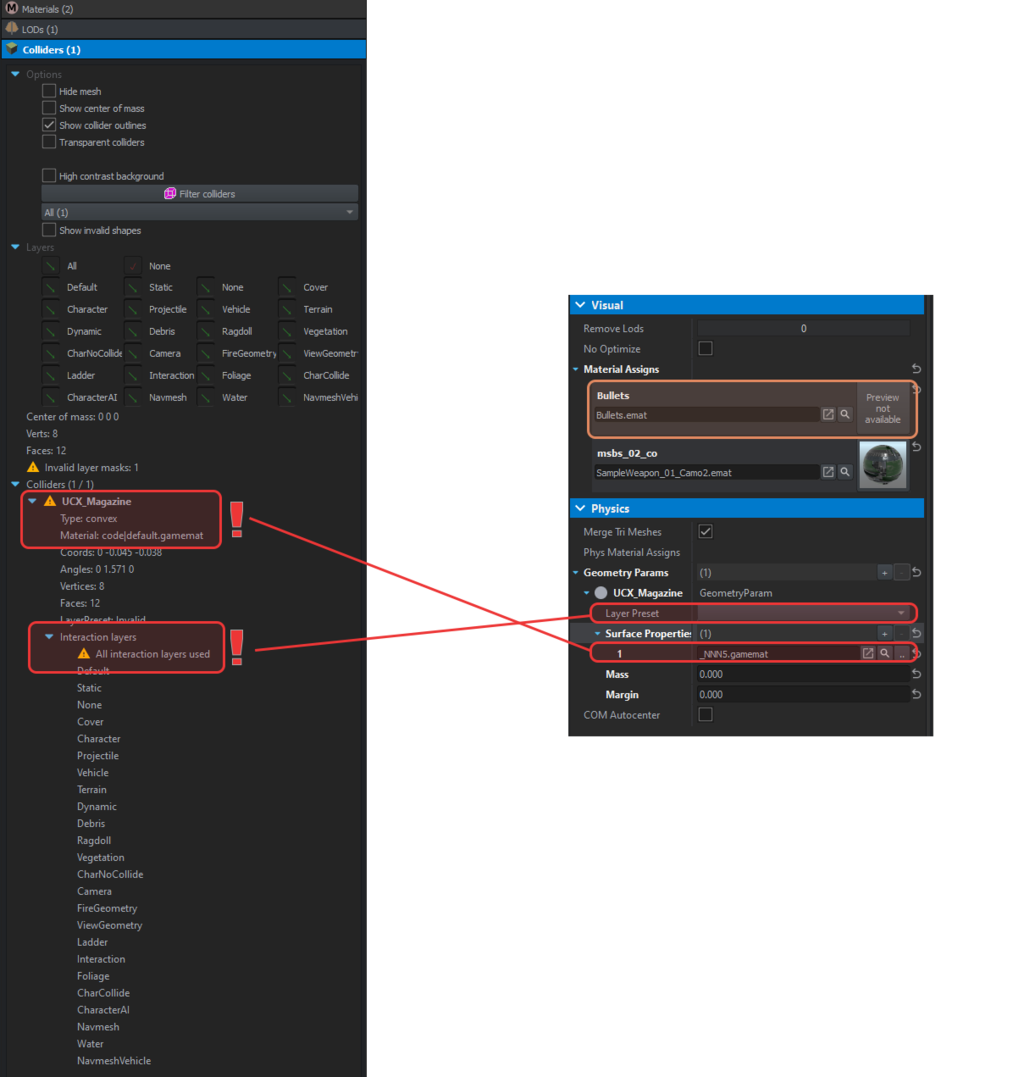
Colliders & Materials Check
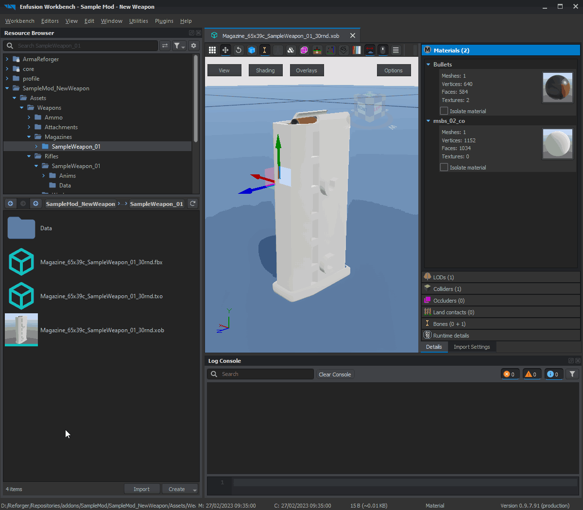
After the initial import is done, it’s time to ensure that materials and colliders are using the correct settings. By default, Enfusion will try to assign materials based on the name of the assigned texture in the mesh. If it fails to find the texture, a new dummy material (see the area marked in orange on the screen below) will be created next to the FBX model.
There are two typical errors when it comes to collider configuration:
Warning
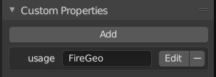
- Make sure that you have “usage” property defined in the collider object properties:
- Make sure that the correct material is assigned to all the colliders:
More info can be found on Arma Reforger:FBX Import.
Skeleton & Hierarchy
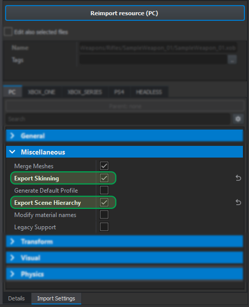
Next, we will take care of the bones. In this case, the magazine object has only empty objects (snap points), and to import them, checking the Export Scene Hierarchy in the Miscellaneous section of the Import Settings tab should be enough.
For skinned assets like rifles, the Export Skinning option should be used instead. It’s also useful to know that Export Scene Hierarchy is not necessary when the Export Skinning option is selected.
The process of setting Export Scene Hierarchy on the magazine is showcased below, followed by the analogous process of using Export Skinning on SampleWeapon_01.xob.
If, for some reason, you don’t see the bones icon on SampleWeapon_01.xob even after checking Export Skinning and reimporting the resource, make sure that you have properly skinned your model in the 3D software of your choice.
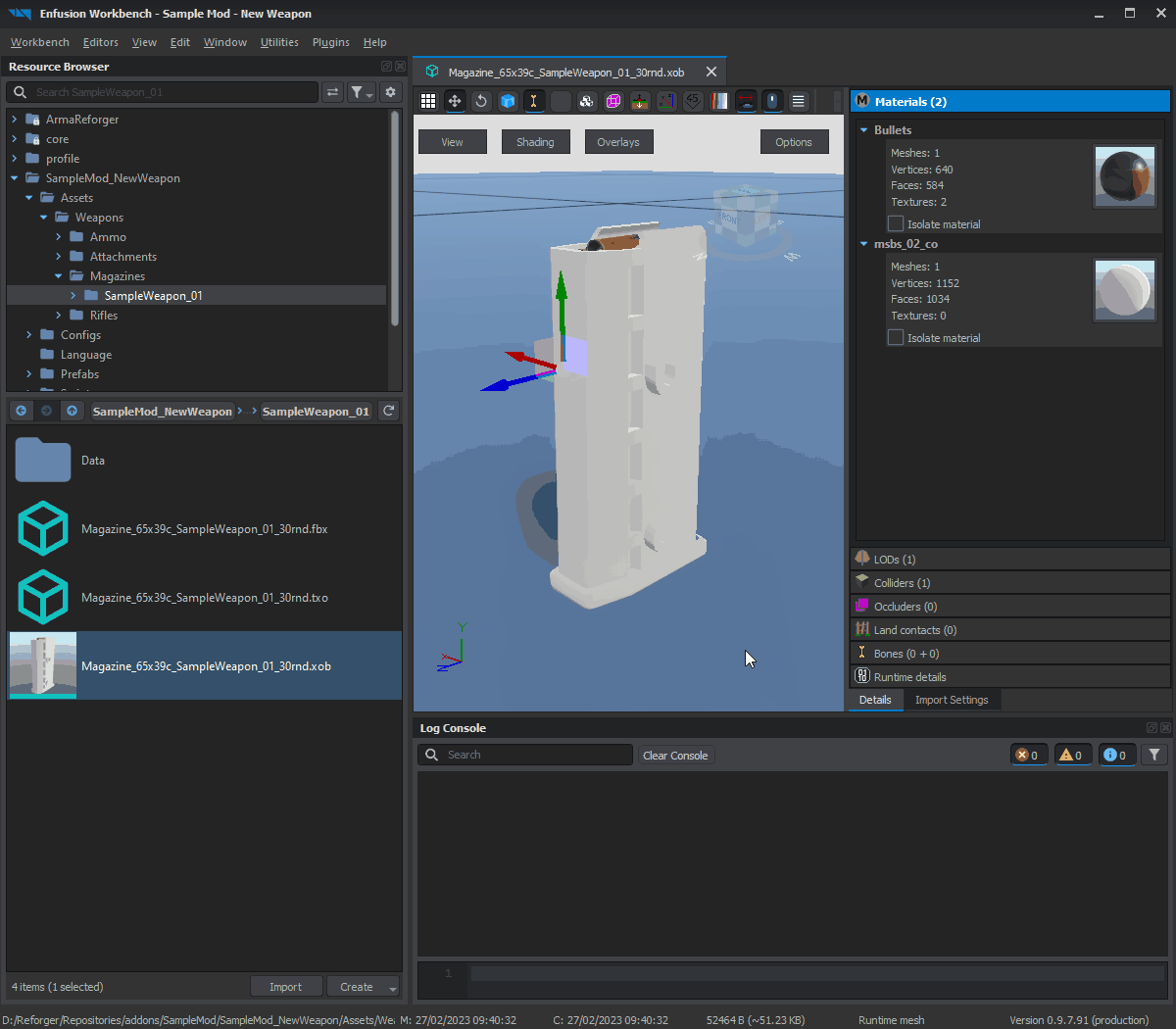 ^ Importing hierarchy on magazine
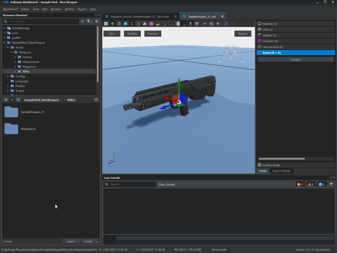 ^ Importing skinning on weapon
Info
Import Settings Tab:
Info
Changes made in Import Settings tab are only applied to the model after manually reimporting the model via Reimport resource (PC) button.
Texture Import
In principle, you can use the same procedures as those described on the Weapon Modding page.
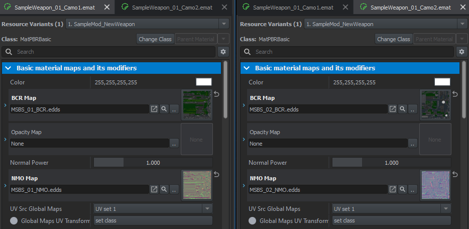
By default, Workbench should already create some of the materials based on their material name in the FBX. So, in the case of SampleWeapon_01.xob, there should already be some emats that need to be properly configured.
- SampleWeapon_01_Camo1.emat material with two textures:
- SampleWeapon_01_Camo1_BCR - Base color + Roughness
- SampleWeapon_01_Camo1_NMO - Normal map
- SampleWeapon_01_Camo2.emat also with two textures:
- SampleWeapon_01_Camo2_BCR - Base color + Roughness
- SampleWeapon_01_Camo2_NMO - Normal map
 Since in this example the magazine shares textures with the rifle itself, it is necessary to adjust the textures accordingly. To do this, double-click on the XOB file of the magazine to open it in a new Resource Manager tab. After that, you can set up the materials that were previously created for the weapon.
Materials can be assigned in two ways:
- Drag and drop the desired material onto the material icon in the Materials tab.
- This action will automatically reimport the model with the selected material.
- Change the Material Assign in the Visual section of the Import Settings.
- It will be necessary to click on the Reimport resource (PC) button after applying changes.
TODO: See the next step: Prefab Configuration.